
I'd like some confirmation on adding the large etti cap bank onto the sf300 amp speedo. I have a tight spot to fit it into and want to make sure it'll be ok to simply add a short wire ( a couple of inches) from the positive and negative joints (the solder joint where the two leads join going into one before the bullet) and then simply solder the cap board to them???
-
-
SAM_0312.jpgSAM_0313.jpgSAM_0311.jpg
That's basically what I did. I ran a loop from one positive, through the cap bank, then back to the other positive, then did the same for the negative. This serves the purpose of paralelling the power wires at the same time, which is necessarry according to the instructions. Keep them as short as possible, but I doubt it matters much if you go a bit longer. This worked flawlessly for me this past season.My private off road rc track
https://www.youtube.com/watch?v=XC3H...yaNZNA&index=8 -
Thanks mate. If already have them joined, one wire off the joint going to cap bank will be fine shouldn't it???Comment
-
I would say so.Originally posted by millzee View PostMy private off road rc track
https://www.youtube.com/watch?v=XC3H...yaNZNA&index=8Comment
-
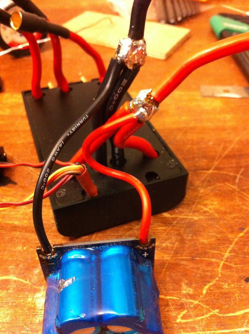
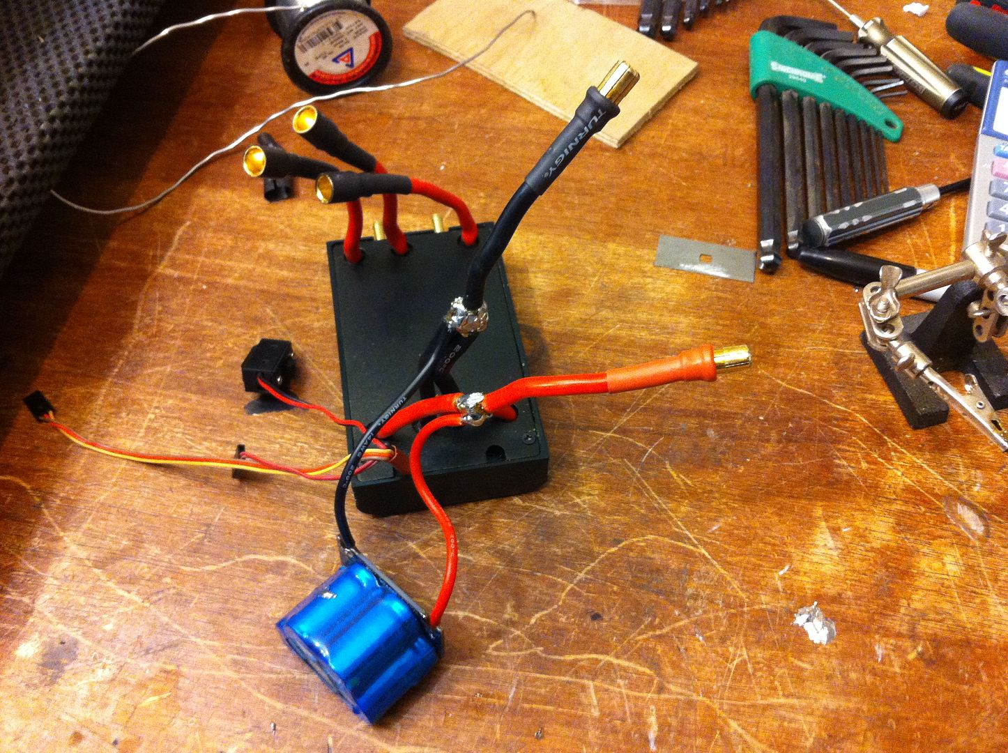
I made the connection and am hoping it'll do the job required, does it all look correct??
Comment
-
Those solder joints seriously need to be done properly, that is a failure point waiting to happen. You should never rely on solder to make the mechanical joint. The wires need to be wrapped around each other then soldered.
Those are also cold joints you have there, either not enough heat or the wires moved while they were cooling. A good solder joint should be very smooth and shiny, not granular, dull, rough and lumpy.
Needs to be fixed before use or you may have a very short, smelly first run.If my boats upside down then who owns the one I thought I was driving the last two laps?
Comment
-
MR. SH; how do you wrap the 12 gauge wires being they're thick? The only thing that comes to mind is stripping more insulation off the wire and keeping the 2 wires woven. I wonder if stuffing the wires into each other would work. Ok, a light bulb went off; if I cut half the wire off on each wire and dove taiing the 2 to make a smooth surface or is this a PITA!? Thanks!!Comment
-
Strip enough insulation to wrap or twist them together, I've done it with 8 and 10 gauge wire. The solder joints will be much longer than what is shown above, doesn't matter though, much better than having solder provide the only strength to the joint.If my boats upside down then who owns the one I thought I was driving the last two laps?Comment
-
Cheers, I'll redo the soldering. The leads to the cap bank will do the job won't they?Comment
-
I'm with Siberianhusky. I wouldn't run it like that. The cap banks don't take a ton of current, so you can get by with piggybacking a solder joint on them. The problem I find with trying to solder something like that in the middle of a run, is that the heat quickly dissipates both ways along the wire and it's tough to get the solder to flow and bond. I'm pretty sure those wires are 8 gauge(much bigger than 12), not sure if you could fit them both into the bullet, but even if you grind open part of the cup(in the bullet) and fit them both in it would still be better. I'm not sure what you're running this in, but if it's even going to come close to the 300 amp rating, I wouldn't want to rely on a single bullet to carry all that anyway..........My private off road rc track
https://www.youtube.com/watch?v=XC3H...yaNZNA&index=8Comment
-
-
cap bank addition.jpgMy Swordfish 300A has been working perfectly on 8S without a capacitor bank but I'm stepping up to 10S now and I'm wondering if the capacitor bank is "mandatory" on a 10S setup? I used a soldering station and bonded both red wires together using 850 degrees and once the solder was very fluid, I used hemostats to press the wires together while removing heat and allowing them to cool down/lock into place. If I go with a capacitor bank, I'm thinking of using this http://www.offshoreelectrics.com/pro...230007&cat=136. Since I run 10S1P and 10S2P, depending on the what I'm doing that day, it's nice having two sets of battery leads. Using the 8mm bullet connectors to go between the capacitor board and the wires going into my battery leads (4" wire leads) seams like an easy way to add the capacitors. The capacitor bank would be approximately 3 to 4" away from the ESC as they would be at the end of the stock wire length, but I'm assuming that's not a problem as that seems to be the intended design. ?Comment
-
Iv'e been running mine on 8 and 10s saw set ups in my mono and working fine with no cap banks.
MarkComment
-
Thanks for the information! The manual says "Strongly recommended over 10S" and I'm only planning on running 10S. I'm also not planning on doing backflips and have my ESC start timing to low to prevent current spikes. The last boat I had this ESC in was hitting 160A and quickly settling to 140A during the straight aways so maybe I can get by without a cap bank.Comment
-
Low timing does not prevent current spikes. Current spikes are caused by load, meaning the prop size, hull weight and how hard you pull the trigger. Low current spikes do not always mean low ripple currents. Do you need a cap bank? What is your ripple current? If it peaks over 10% of pack voltage then you will benefit from one regardless of "how it runs". So much depends on battery quality and wire length - just because one guy gets away with it does not mean you can in your boat. ESC longevity is what matters here, along with overall system efficiency. The right cap bank can give better performance on the pond along with longer ESC life.
The cap banks on a pigtail may not work as well as you think, especially on higher rpm/hjgh draw setups. The 'best' is always with each cap soldered across the power wires. This isn't always needed, but it is always the most efficient. Just adding any old cap bank does not mean you have solved the problems.
/ERROR 403 - This is not the page you are looking for
Comment


Comment